
What Root-Cause Investigation Should Include After Repeated Equipment Breakdowns
By Ventarus Engineering Services Ltd, engineering services for Chester, North Wales and Merseyside
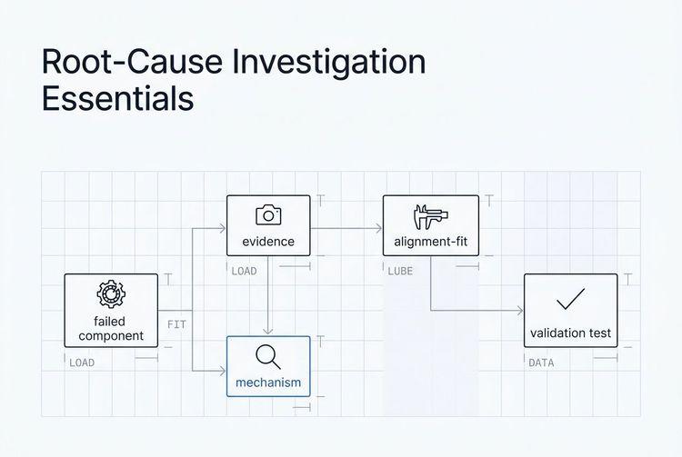
When equipment breaks down more than once, the job is not to guess faster. It’s to find the real failure mechanism before you turn a repeat repair into a repeat problem. A proper root-cause investigation should answer more than “what broke?” It should answer why it broke here, under these conditions, in this way, and why the previous fix didn’t stop the next equipment breakdowns.
That means starting with the failed part as evidence, not scrap. It means checking the operating conditions the machine actually saw, not the ones written on the drawing. And it means not treating a redesign as a permanent solution until the failure cause has been proven and the new arrangement has been validated in service.
Make the equipment safe, then preserve the evidence
The first step is containment, not diagnosis. If the machine is still live, isolate it, make it stable, and protect people before anyone starts pulling parts apart. That includes electrical isolation, lockoff where re-energisation is possible, release of stored energy, isolation of pressurised lines, support for parts that could fall, cooling hot components, and controlled access where needed.
This is where people get rushed. Production wants the line back. Maintenance wants to see the damage. But a useful root-cause investigation can fall apart if the evidence is destroyed in the first hour.
Before cleaning or dismantling anything, record the failed part in place and as received. Photograph the component, the surrounding machine, fasteners, supports, seals, welds, shafts and housings. Mark its position and orientation. Note loose bolts, scratches, distortion, leakage, contamination and signs of heat. Keep related pieces together and label everything clearly.
Do not clean a failed bearing before the first inspection. That matters because cleaning can remove the clues you need to tell fatigue from contamination, overload, poor fit or installation damage. If a temporary repair is needed to restore production, that’s fine. Just don’t throw away the evidence if you may need a proper failure analysis later.
Evidence-preservation checklist
Use a simple checklist before disassembly:
- Photograph the failed part in place and as received.
- Photograph the machine, guards, supports, fasteners, seals, shafts and adjacent parts.
- Record the part’s position and orientation.
- Note loose bolts, wear, distortion, leakage, contamination and heat marks.
- Preserve fracture and contact surfaces from unnecessary handling.
- Avoid cleaning failed bearings before the initial inspection.
- Take lubricant samples in clean, labelled containers.
- Label removed parts and keep related pieces together.
- Record the disassembly method.
- Record who removed the part, when, from which machine and after how many operating hours or cycles.
A failed component is evidence. If you machine it, weld it, grind it or bin it too soon, you may lose the one thing that would have shown you the real cause.
Reconstruct the failure pattern, not just the latest break
A single broken part rarely tells the whole story. Repeated failures are a pattern problem, so the investigation should look at every previous event, not only the latest one on the shop floor.
Start by collecting the basics for each failure: asset and component ID, failure date and time, operating hours or cycles since installation, where the failure occurred in the assembly, what the first visible failure mode was, and whether the same physical feature failed each time. Also capture the process state at the time. Was it startup, steady running, changeover, cleaning, washdown, blockage clearing or shutdown?
This is where the picture starts to sharpen. A failure that happens every time at startup points somewhere different from one that appears only under steady load. A failure that shows up after changeover or washdown may point to process, contamination or handling. If the failed part changes but the underlying damage looks the same, the real problem may be outside the part itself.
Failure-history questions that matter
Ask these questions of each repeat failure:
- Does the same component fail, or does the same condition damage different components?
- Does it fail in the same location or on the same side?
- Does it happen after a similar time or number of cycles?
- Is it tied to a product, speed, load, temperature, operator, shift or changeover?
- Did it start after a process change, repair, supplier change or installation event?
- Is the replacement part failing earlier than the original?
- Is the failure mode really the same each time?
- Did the previous fix address the cause, or only get the plant running again?
A repeated failure at the same point may point to a stress concentration, poor geometry, inadequate clearance, weld detail, corrosion or overload. If the failure appears in different places around the machine, look wider. Contamination, poor lubrication, incorrect fit, bad installation or a changed duty cycle can spread damage across the system.
That’s the part worth your afternoon. If you only examine the newest broken piece, you can miss the pattern that has been staring at you for months.
Identify the failure mechanism before you talk redesign
A useful root-cause investigation has to move from symptom to mechanism. “The bracket broke” or “the bearing failed” is a description, not an answer.
The physical mechanism could be fatigue crack growth, one-time overload, bending, wear, fretting, corrosion, thermal damage, lubrication starvation, contamination, misalignment, loosening, weld defects, material mismatch, bad heat treatment, installation damage or electrical damage in rotating equipment. The point is not to guess one and run with it. The point is to find the evidence that supports one mechanism over the others.
For safety-critical, costly, unusual or disputed failures, testing may be needed. The right tests depend on the part and the suspected mechanism. Useful methods can include visual and dimensional examination, fracture-surface inspection, metallography, hardness testing, chemical composition analysis, mechanical testing, corrosion or aggressive-environment testing, hydrogen analysis where relevant, non-destructive testing, scanning electron microscopy, and simulation or testing under representative service conditions.
You do not need every test. You need the tests that separate one explanation from another.
For example:
- Fatigue needs a different corrective action from a one-time overload.
- A material defect needs a different response from a correct part that was overloaded.
- Corrosion-assisted cracking needs a different response from simple mechanical fatigue.
- A weld defect needs a different response from an excessive process load.
- A wrong material or heat treatment needs a different response from a poor installation method.
That’s the real value of the test work. It keeps you from spending money on the wrong fix.
What good evidence should show
A defensible conclusion should connect the physical evidence to the mechanism. The team should be able to say:
- Where the crack or damage started.
- Whether the damage grew gradually or happened suddenly.
- Whether the surface shows cyclic growth, overload, rubbing, corrosion or impact.
- Whether the dimensions and geometry match the drawing.
- Whether the material and treatment suit the actual service.
- Whether the part saw a condition outside its intended envelope.
If the answer is just “the material was weak,” keep going. That’s not a conclusion. It’s a shortcut.
Check load, alignment, fit and installation
A part should not be redesigned until you’ve tested whether it was ever loaded the way it was intended to be loaded. In real plants, the machine often sees more than the drawing assumes.
Start with load. Look at static and working load, shock loads, impact, torque, start-stop cycles, acceleration and deceleration, jamming, blockages, belt and chain forces, gear and coupling forces, pressure and pressure spikes, thermal expansion, and any new load created by a change in product or throughput. Also check whether the component is being used as a guide, stop, support or lifting point when that was never part of the design.
Then check whether a previous modification shifted the load into another part. A stronger bracket can push the problem into a shaft, weld, frame, mounting point or bearing. That’s how one fix becomes another failure.
Alignment and deflection
For rotating equipment, check angular and offset misalignment. Laser shaft alignment, coupling condition, belt alignment, vibration patterns, temperature differences between bearing housings, seal wear, foundation movement, soft foot, distorted feet, shaft runout, housing rigidity and deflection under operating load all matter here.
Misalignment can create friction, heat and extra load. In bearings, it can show up as one-sided raceway damage or edge loading. But the useful question is not just whether it is misaligned. It’s why.
Was the machine poorly installed? Are the supports worn? Has the foundation moved? Is thermal growth being ignored? Is the load higher than expected? Has the mounting arrangement failed to allow movement?
Fits, clearances and machining
A root-cause investigation should also check the mechanical fit. Measure shaft and housing diameters, roundness, taper, seat condition, shoulder squareness, bore geometry, internal clearance, preload, shim arrangement, fastener condition, keyways, locknuts, adapters, burrs, raised edges and local high spots. Verify orientation too.
Timken guidance recommends checking shaft and housing size, roundness and taper with suitable certified gauges. SKF also highlights fits, support surfaces, bearing seats and mounting procedures as contributors to premature failure.
Here’s where people get caught. A part can look like a lubrication failure when the real issue is excessive preload. It can look like a machining issue when the real issue is a poor fit. Appearance is a clue, not a verdict.
Installation and handling
Check the method used, not just the final position. Was the correct tool used? Were forces applied through the correct ring or structural member? Was brute force or heating used? Was the part dropped, tilted or contaminated? Were seals installed the right way round? Was a directional bearing installed backwards? Were clearances and preload set correctly? Were the mounting surfaces clean and undamaged? Was the part supported properly during tightening?
Poor handling can introduce nicks, dents, cage damage, distorted retainers and local spalling. If the same part keeps failing and the install method never changes, the breakdown will probably keep returning.
Review the operating conditions, lubrication and maintenance system
The part has to be judged in the environment it actually lives in. Not the drawing. Not the spec sheet. The real working conditions.
Start with the operating data. Look at speed, speed variation, load variation, peak load, temperature at startup and steady state, ambient temperature, vibration and noise history, pressure and flow where relevant, duty cycle, number of starts or cycles, washdown, dust, moisture, chemicals, airborne contamination, product build-up, debris, control settings, alarms, bypasses and operator workarounds.
A component can be fine in one duty and wrong in another. If the process changed, the old answer may no longer fit.
Lubrication and contamination
Check lubricant type, grade, viscosity, additives, quantity, relubrication interval, application method and whether the lubricant reaches the contact surface. Look for overfilling, underfilling, water, dust, metal, product or chemical contamination, seal condition, filter condition, oxidation, discolouration, burning, separation and unusual consistency.
SKF’s broad bearing guidance points to lubrication, contamination and application or mounting as the big groups behind most bearing damage. Those figures are only handbook-level estimates for bearings, but the direction is clear. Lubrication and contamination are common places to look.
Timken also notes that too much grease can cause churning and high temperature, while too little lubrication can cause heat, wear and surface damage. Excessive preload can look similar to inadequate lubrication, so don’t decide from appearance alone.
Maintenance and human factors
The maintenance system also needs review. Was there a clear inspection or lubrication procedure? Was it practical with the access available? Were the right tools, gauges and lifting gear on hand? Were findings recorded and acted on? Were parts stored and handled properly? Were intervals based on actual condition, or copied from another machine? Did production pressure lead to skipped checks or temporary fixes?
And don’t stop at “operator error” or “maintenance error.” If people made mistakes, ask why the mistake was possible. Poor access, unclear instructions, missing tools, weak training, bad guarding, production pressure or an awkward design may be part of the cause too.
If this feels like a lot, it is. Start with the one area that fits the evidence best, then work outward.
Decide whether to repair, modify or redesign, then prove it works
This is the point where many teams jump too soon. They see a broken part and want a stronger one. That can be the right answer, but only after the investigation shows the existing part cannot handle the real duty or cannot stay reliable in the real environment.
Use the evidence to decide.
When repair is enough
Repair may be right when the failure came from an isolated event, the design is still suitable, the damage is local, and the repair can restore strength and function safely.
When modification makes more sense
Modification fits when the asset is still valuable but needs reinforcement, better access, altered guarding, improved support or a revised mounting arrangement. A bespoke bracket, frame, guard, platform or support can solve a demonstrated problem without replacing the whole machine.
When redesign is justified
Redesign is the better call when the part is under-capacity for the real load or duty cycle, the geometry creates a repeated stress concentration, the material or manufacturing route can’t deliver the needed performance, the operating envelope has changed permanently, or the problem can’t be controlled through better alignment, installation, lubrication, support or controls.
But a redesign should also be checked for secondary effects. A stronger part can move the weak point somewhere else. That’s why the review has to include adjacent parts, load transfer, fit, corrosion, temperature, access, inspection and safe installation.
What to review before approving the new part
Before you install a new design, check:
- Strength and stiffness.
- Fatigue duty and cycle count.
- Shock and overload cases.
- Deflection and load transfer into adjacent parts.
- Material grade and treatment.
- Weld design and inspection needs.
- Corrosion, contamination and temperature exposure.
- Fit, clearance, preload and thermal expansion.
- Installation and removal access.
- Inspection and lubrication access.
- Guarding and safe access.
- Compatibility with controls, sensors and interlocks.
- Whether the part can be made and inspected consistently.
- Whether the redesign creates a new weak link.
Validate the solution
A permanent solution is only as good as the proof behind it. Set acceptance criteria before the modification goes in. Then confirm the drawing, material, dimensions and fabrication quality. Inspect welds, surfaces, fits and mounting points. installation, alignment, fasteners , guards and safe access. Record baseline vibration, temperature, noise, leakage and performance. Run the equipment in representative production conditions. Monitor it during the trial. Reinspect after an agreed period or number of cycles. Compare the results with the original failure evidence. Update the drawings, maintenance instructions, inspection frequency and spare-part records.
That final step matters more than people think. If you don’t document the change, the next failure starts from zero again.
What this means in practice
A useful root-cause investigation is not a hunt for the most obvious broken part. It’s a careful check of the mechanism, the conditions, the fit, the load, the installation, the lubrication and the maintenance system that allowed the failure to repeat.
That’s also why a redesigned part is not automatically a permanent solution. It only becomes one when it removes or controls the proven cause, fits the real working environment, doesn’t push the problem into another component, and proves itself during monitored operation.
If you’re dealing with repeated equipment breakdowns, that’s the point worth holding onto. Fix the cause chain, not just the last break.
Ventarus Engineering Services supports manufacturers and industrial sites with assessment-led breakdown support, damaged component repairs, fabricated replacement parts, welding, reinforcement, equipment modifications and root-cause investigation where required. If you’ve got drawings, photos, samples or even just a problem that keeps coming back, we can help you work through what needs repairing, what needs modifying and what needs replacing.
FAQ
Should a repeatedly failing part always be redesigned?
No. First prove that the part is actually under-designed. Repeated failure can also come from overload, misalignment, contamination, wrong lubricant, incorrect fit, poor installation, inadequate support or a changed process condition.
What should we do with the failed component?
Preserve it, photograph it, label it and record its orientation and surroundings. Don’t clean, weld, machine or discard it before the initial inspection if a failure analysis may be needed.
How can we tell whether a failure was fatigue or overload?
Look at the fracture or damage pattern, where it started, the surrounding deformation and the service history. If the answer matters, use the right testing instead of relying on appearance alone.
When is laboratory testing worth the effort?
It’s most useful when the failure is safety-critical, expensive, unusual, disputed, fracture-related or tied to a suspected material defect. The test should help separate competing explanations, not just add paperwork.