
How to Handle Obsolete Machinery When Spare Parts Are Unavailable
By Ventarus Engineering Services Ltd, engineering services for Chester, North Wales and Merseyside
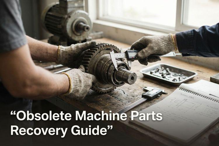
An older machine has failed, the OEM part is obsolete, and production can’t wait for a catalogue fix. That’s the situation this guide is for. If you’re dealing with obsolete machinery and spare parts unavailable, the practical question isn’t just “can we make something?” It’s “what’s the safest route back to service without turning a repair into an uncontrolled redesign?”
The most practical recovery path is usually assessment-led. Make the asset safe, work out why the part failed, decide whether the original function and interfaces can be recovered, then repair, adapt, reverse engineer, or fabricate a replacement component where that is technically justified. Inspect it, test it, and document the repair before you return the machine to production.
That sounds like a lot, but the job gets smaller if you take it in order. Start with safety, then failure definition, then the recovery route.
1. Make the machine safe before you touch the part
The first decision is not how to replace the component. It’s how to keep people from getting hurt while you work on a live problem.
Stop the machine and prevent unauthorised restart. Identify all relevant energy sources, including electrical, hydraulic, pneumatic, mechanical, thermal, and stored energy. Isolate and lock off the energy sources where the risk assessment requires it. Control access to the work area, and use a permit-to-work or other formal safe system where the task is high risk.
If people need to work near hazards, provide safe access, temporary guarding, or other physical controls. Make sure the people doing the work are competent and have the information, instruction, and training they need. Do not remove a guard or bypass an interlock just to make diagnosis easier unless that has been specifically risk-assessed and controlled.
This matters because maintenance work has to be carried out safely, and the machine has to be maintained in efficient working order and good repair. The machine is not ready just because a new part is bolted in. It also has to be safe for setup, normal operation, blockage clearing, breakdown repair, and planned maintenance.
If this feels like the slow part, it is. It’s still the part that keeps the rest of the job from getting expensive in the wrong way.
2. Define the failure before you pick a recovery route
Do not assume the broken part is the whole problem. A component may fail because of overload, misalignment, vibration, fatigue, corrosion, poor lubrication, excessive temperature, incorrect adjustment, electrical damage, or a change in the production duty.
Before you disturb the evidence, record the machine make, model, serial number, and asset identification. Note the component name, part number, and any markings. Capture the machine function affected, what happened immediately before the failure, and the operating conditions where relevant, including speed, load, pressure, temperature, duty cycle, and material being processed. Also record recent changes to process, tooling, settings, maintenance, or the control system, plus any previous failures of the same component.
Don’t ignore the parts around the failure. Check the condition of mating parts, bearings, shafts, mounts, fasteners, guards, and adjacent structures. Take photographs showing the installed position and the damage before cleaning or dismantling. Gather any drawings, manuals, inspection records, maintenance history, or earlier repair notes you have.
Where possible, preserve the failed component. Don’t discard it, weld it, grind it, straighten it, or clean it aggressively before you decide whether it’s needed for failure analysis or as a dimensional reference. When you dismantle it, record markings and orientation. If you have an unused, less-worn, or equivalent component, compare it with that too. A used part can help with geometry, but it may already reflect wear, deformation, or a previous repair.
Here’s where most people stall, and it’s not the part itself. They jump straight to replacement before they know whether they need a repair, a copy, or a correction.
3. Choose the right route: repair, copy, adapt, or redesign
The right answer depends on function and condition, not on whether the OEM catalogue still lists the part.
If damage is local and the original material and geometry still look reliable, a repair, weld repair, reinforcement, or machining may be enough. If the component is simple and you have a sound sample or a reliable drawing, a bespoke replacement component may be the cleanest option. If the part is complex, undocumented, or has legacy geometry, reverse engineering from measurement or scanning is usually the better route.
There are also times when the original design has a known weakness or the duty has changed. In that case, an improved replacement or controlled modification may make sense. If production has to restart while a permanent part is being developed, a temporary engineered solution can keep the line moving, but only with defined limits, a risk assessment, supervision, inspection frequency, and a removal or replacement date.
If you cannot establish the material, geometry, load path, or safety function, stop and get specialist engineering advice. Don’t manufacture a guessed part for a safety-critical or high-consequence application.
A temporary repair should not quietly become a permanent one. It needs a purpose and a review point.
4. Define what the part has to do before you measure it
A good repair starts with the function, not the shape.
Before you draw or measure anything, define the component’s interfaces with shafts, bearings, frames, brackets, housings, guards, or tooling. Identify the datum surfaces and the features that control alignment. Confirm hole patterns, bolt sizes, keyways, splines, threads, shoulders, locating features, clearances, and movement envelope.
Then define the operating duty. That includes loads, impact, vibration, speed, pressure, duty cycle, temperature range, thermal expansion, contact with water or cleaning chemicals, process chemicals, food products, dust, or abrasive material, plus wear surfaces, corrosion exposure, and any needed surface protection. If relevant, include material, hardness, heat treatment, coating, finish, welding, machining, forming, or assembly constraints. Don’t forget the relationship to guarding or safety-related control functions.
You don’t necessarily need a finished drawing at this stage. A drawing helps, but measurements, photographs, a sample, or an on-site discussion can be enough to start. The more you know about the duty and failure history, the less likely the replacement is to reproduce the same weakness.
5. Capture the geometry with the right method
Reverse engineering is not one single measurement method. It’s a practical mix of measurement and digital reconstruction.
For simple parts with accessible features, conventional dimensional measurement may be enough. For high-precision features, datums, and primitive geometry, probes or coordinate measurement may be better. For complex surfaces, larger parts, and freeform geometry, laser scanning or structured-light scanning can help. If the features you need are internal, computed tomography may be the right choice. Often, the best answer is a combination of contact and non-contact methods.
Choose the method based on the part’s size, geometry, required precision, accessibility, and budget. Scanning is especially useful when the original design data is missing, locked in a legacy format, or hard to recreate by hand.
If the component is damaged or worn, don’t just measure the broken area. Measure the mating parts, the mounting arrangement, and the surrounding envelope too. A replacement that matches the failed part but not the actual machine interface may still fail at installation or during operation.
Good practice is to establish datums and a repeatable orientation, record the method and equipment used, separate measured features from inferred ones, identify worn or distorted surfaces, take enough measurements to distinguish design intent from wear, and retain the original scan, point cloud, or measurement record as evidence.
One thing not to do, because it causes trouble later, is pretend there’s a universal tolerance. There isn’t. The right tolerance depends on the feature, the part, the method, and the manufacturing process.
6. Turn measurements into usable engineering data
This is the part where a scan becomes something you can actually manufacture from, but it’s not automatic.
A practical digital workflow is to capture the part or the relevant interfaces, align the data to the chosen datums, clean noise and irrelevant points, stitch multiple point clouds into one coherent dataset, create a mesh or other usable three-dimensional representation, identify regions of interest, fit geometric primitives or sketches, reconstruct a solid, surfaced, or parametric CAD model, compare the model with the scan or measurement data, review it against the machine’s functional requirements, and issue a controlled drawing or manufacturing definition.
The scan is not the finished CAD model. Point clouds and meshes usually need alignment, cleaning, meshing, smoothing, and interpretation. The resulting model should be checked for completeness and accuracy before it is used for manufacture.
Where multiple scans are involved, they should be stitched into one coherent dataset. Where the part has regular features, separate intended geometry from local damage or wear instead of copying every defect. That comparison step matters. It can show how the component degraded and whether a modest design improvement is justified.
This is also where bespoke replacement components stop being a vague idea and become a controlled engineering task. The point is not to copy a damaged part blind. It’s to recover the needed function and interfaces while understanding what the old part was actually doing in service.
7. Investigate material and failure, not just shape
Geometry alone does not make a durable replacement. Two parts can match in size and still behave very differently if the material, hardness, heat treatment, surface finish, or manufacturing method differs.
Failure analysis should consider distortion or unwanted deformation, fracture and crack initiation, corrosion and chemical attack, wear, abrasion and fretting, fatigue from cyclic loading, mechanical overload or impact, thermal degradation, electrical damage or current paths, residual stresses from fabrication or welding, and misalignment, incorrect assembly, or inadequate support.
A useful sequence is to define what failed in operational terms, collect evidence and operating information, identify the damage modes, identify possible damage mechanisms, test which mechanisms actually occurred, separate primary damage from secondary damage, identify possible root causes, test or evaluate the most likely root cause, select and implement corrective action, and evaluate whether it worked.
Stay open-minded here. A crack may be the symptom, fatigue may be the mechanism, misalignment or excessive cyclic load may be the cause, and the stoppage may be the consequence. Those are not the same thing.
Also look at the operating environment. The stressors may be mechanical, chemical, electrochemical, thermal, radiation-related, or electrical. For repeat failures, a more formal failure mode and effects review can help you weigh failure modes, local and overall effects, likelihood, detectability, and possible controls.
This is the step that stops you from rebuilding the same problem twice.
8. Choose the manufacturing route and write the replacement definition
The manufacturing method should fit the geometry, material, quantity, accuracy, and deadline.
For a bespoke replacement component, the manufacturing definition should state the material grade or an engineering-approved equivalent, required thicknesses and critical dimensions, datums and tolerances for mating features, surface finish or coating, heat treatment or hardness, welded joints and joint preparation, distortion controls, machined, drilled, formed, or fabricated features, fastener type and fit, inspection points and acceptance criteria, and any safety-related features that must not be altered.
Ventarus supports industrial fabrication, replacement machine parts, frames, brackets, supports, guards, platforms. Its welding capabilities include MIG and TIG welding, including fabricated assemblies, on-site repairs, structural repair, and reinforcement. It can work from drawings, measurements, photographs, samples, or an on-site discussion.
That said, not every obsolete part should be made by welding or broad fabrication. A precision shaft, bearing, pressure-containing component, safety component, or highly loaded rotating part may need specialist machining, material testing, balancing, heat treatment, or independent inspection beyond a basic fabricated repair.
That’s the part worth your afternoon. The rest can wait a month.
9. Inspect, fit, and validate before full production use
A part can fit and still be unsafe or unreliable. Validation should match the consequence of failure.
Before installation, check the critical dimensions against the controlled drawing, confirm mounting-hole positions, datums, clearances, and interfaces, check material and treatment documentation where the duty requires it, inspect welds and fabricated joints with an appropriate competent inspection method, check for distortion, sharp edges, incomplete finishing, or interference, and confirm the part doesn’t block guards, access routes, or emergency controls.
During fit-up, confirm alignment without forcing the part into position. Check shaft, bearing, coupling, or bracket relationships. Check free movement by hand where appropriate. Confirm fastener engagement and locking arrangements. Verify that guards and interlocks can be refitted and work correctly.
For commissioning, use a controlled first run under the conditions permitted by the risk assessment. Low-speed, hold-to-run, or no-load checks may be appropriate. Watch for abnormal noise, vibration, heat, movement, leakage, rubbing, or distortion. Check the part and adjacent components again after the first run. Increase the operating duty in stages where that makes technical sense. Record the inspection, test result, operating conditions, and any follow-up action.
There is no universal vibration, temperature, or load threshold you can drop into a generic article and call it safe. The acceptance limit has to be specific to the application.
10. Complete the safety and conformity review
A repaired machine must be suitable for its intended purpose and operating conditions, maintained in a safe condition, and supported by a safe system of work.
The key distinction is between ordinary maintenance and a substantial change. Routine maintenance or like-for-like work can include servicing, repainting, changing motors, replacing a guard with an essentially identical new guard, replacing an original safety-critical part with a newer, better part where it is installed into the control system in the same way as before, or rebuilding machinery to its original specification with replacement parts, including newer designs that remain equivalent in function.
But a modification needs closer review if it changes the machine’s function, increases performance, introduces significant new hazards, or replaces an existing method of control with a materially different one. Automatic programmed operation replacing a previously manual control method is one example of a very substantial change.
Ask the hard questions. Is the component genuinely equivalent in function and interface? Does the change introduce a new hazard or operating mode? Does it change speed, capacity, force, reach, or control logic? Does it affect a safety-related control system? Was the change foreseen or approved by the original manufacturer? Does another regime also apply, such as lifting equipment, pressure systems, electrical safety, or hazardous-area requirements?
If the answer points to a substantial change, get competent machinery-safety and conformity advice before you put the machine back into service. A routine replacement does not automatically create a substantial modification. But a change that alters function, hazards, or control methods may do so.
The practical rule is simple enough: don’t give yourself a legal answer that the actual machine doesn’t support.
11. Control hot work and fabrication hazards
If the recovery involves welding, cutting, or heating, treat that as a separate job with its own assessment.
The hazards include fire from sparks, molten metal, or heat transfer; explosion from containers, tanks, pipework, or cavities with flammable residues; harmful fumes from paint, primers, coatings, galvanised surfaces, or process contamination; electric shock from welding equipment or damaged return cables; UV and infrared exposure; burns, splatter, and hot components; gas-cylinder impact, leakage, fire, and manual-handling hazards; and welding-induced distortion or damage to adjacent safety-critical parts.
Controls may include isolation and cleaning, removal or shielding of combustible materials, suitable ventilation or local exhaust ventilation, welding screens, protective clothing, eye protection, sound electrical connections, and competent operators. Never apply heat to a container that may contain flammable residue unless it has been properly cleaned and purged under a competent safe system.
MIG and TIG are tools, not automatic approvals. The process has to suit the material and the design.
MIG and TIG are tools, not automatic approvals. The process has to suit the material and the design.
12. Know when a bespoke replacement makes sense, and when to stop
A bespoke replacement is often the right call when the machine is still suitable for the process, the failed component’s function and interfaces can be established, the required material and duty can be defined, the part can be manufactured and inspected within the shutdown or recovery window, the component doesn’t create unacceptable safety or conformity issues, the cost and risk are proportionate to the value and criticality of the asset, and the root cause can be addressed rather than simply copied.
Pause or escalate when the part is safety-critical and its performance can’t be verified, the machine frame, pressure boundary, lifting function, or primary load path is damaged, the material or heat treatment is essential but unknown, the original sample is badly worn or distorted and no sound reference exists, the repair would alter guarding, interlocks, control logic, speed, force, or machine function, the proposed repair needs a new risk assessment or conformity assessment that hasn’t been done, or the machine has other defects that make return to service unsafe.
That’s the real decision point for obsolete machinery. You’re not asking whether the part exists. You’re asking whether the machine can be restored safely and with enough control to hold up in production.
A practical records package for the repair file
Keep the repair file in proportion to the risk, but keep it. Include asset identification and failure description, photographs before dismantling and after repair, original component markings and orientation, measurements, scan data, or inspection notes, failure-analysis findings and the root-cause decision, controlled drawing or CAD revision, material, treatment, and manufacturing information, inspection and test results, installation date and responsible persons, guarding, interlock, and safety checks, any temporary operating limits or follow-up inspections, and updated maintenance instructions and spare-part information for the new component.
That last item matters more than people think. If a bespoke component has been created, keep its drawing, revision, material definition, and inspection requirements so the next replacement doesn’t depend on the same emergency reverse-engineering exercise.
When to bring in outside engineering support
You don’t need outside help for every broken part. But you do need it when the machine is down, the internal team is stretched, and the decision is between guessing and engineering.
A practical support partner can help with assessment-led repairs and breakdown support, fabricated replacement parts, MIG and TIG welding for repair, reinforcement, and fabricated assemblies, bespoke brackets, frames, guards, supports, and access equipment, equipment modifications where an existing asset still has value, and root-cause investigation for repeat failures where that’s needed. Ventarus works from drawings, measurements, photos, samples, or an on-site discussion, so you don’t have to have every answer before you call.
If the failure is urgent, send the machine identification, photos of the installed and failed part, any drawings or manuals, dimensions, component markings, operating conditions, failure history, access constraints, and the shutdown or production window you’re working to. Keep the failed component if failure analysis may still be needed.
FAQ
Can obsolete machinery still be repaired if the OEM no longer supplies the part?
Often, yes. The practical route may be to repair the existing component, fabricate a replacement, or reverse engineer one from a sound sample, measurements, or available documentation. The choice depends on function, material, load, safety, and the condition of the machine.
Do I need the original OEM drawing?
No. A drawing helps, but it isn’t essential. A competent engineering provider may be able to work from measurements, photographs, a physical sample, or an on-site assessment. Without a drawing, the functional and dimensional investigation matters more.
Is reverse engineering just copying the broken part?
No. The process should separate intended geometry from wear and damage, establish the interfaces and duty, and investigate why it failed. A replacement may keep the original interfaces while correcting a confirmed weakness, but that change has to be engineered and validated.
Can a bespoke replacement affect CE or UKCA status?
A routine or like-for-like replacement does not automatically create a substantial modification. A change that alters function, performance, hazards, or control methods may do so. The specific change should be assessed by a competent machinery-safety professional.
How do I stop the same bespoke part failing again?
Investigate the failure mechanism before you finalise the replacement. Review alignment, loads, vibration, wear, corrosion, temperature, lubrication, assembly, and process changes. Record the root cause and update the maintenance plan instead of treating the new part as the end of the job.
Closing direction
Obsolete machinery isn’t automatically beyond recovery, but an improvised replacement is not a maintenance strategy. The safest route is to understand the failure, recover the required geometry and function, manufacture a controlled replacement or repair, verify the machine’s safeguards, and test the result before release.
If you’re dealing with a failed component, an obsolete spare, a recurring breakdown, or a planned shutdown, talk it through with an engineering provider that can assess the machine and decide whether repair, bespoke fabrication, welding, or modification is the sensible next step.